Seyed Masoud Hosseini · Overview · Study log · Weekly summaries · Ideas · Search · Transcript · RSS feed
Embedded Systems, 6502 breadboard computer · Lecture 18 of 29 · 26:10
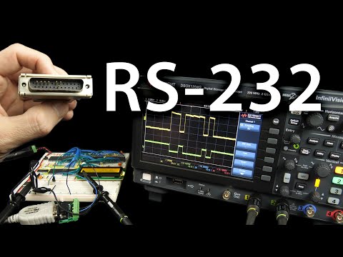
Lecture 18: The RS-232 Protocol
Study guide
What this lecture covers
The lecture explains how the RS-232 serial standard represents bits electrically and frames them into bytes, then uses that understanding to receive serial data on the breadboard 6502 computer without a dedicated UART chip. It follows the earlier 6522 I/O videos and precedes a later video that adds a proper interface chip.
By the end, you can explain why RS-232 needs a start bit, how baud rate synchronizes transmitter and receiver clocks, and how to bit-bang a receiver in software by timing reads against a known clock speed.
Key ideas
- DTE and DCE: RS-232 defines a data terminal equipment (DTE, e.g. a computer) and data circuit-terminating equipment (DCE, e.g. a modem); pin functions like "transmit data" are defined from the DTE's perspective.
- Mark and space voltage levels: a voltage more negative than -3V is a "mark" (binary 1, idle state); more positive than +3V is a "space" (binary 0); the range between is undefined.
- No shared clock: unlike SPI, RS-232 carries no clock signal, so both ends must independently agree on a data rate (baud rate) in advance.
- Start bit resynchronization: every byte begins with a start bit that lets the receiver's clock resynchronize, so small clock drift between transmitter and receiver only has to hold steady for about 10 bit times.
- Frame format: a start bit, a configurable number of data bits (commonly 8, least-significant bit first), an optional parity bit, and one or more stop bits.
- Clock slip: if transmit and receive clocks drift too far apart over many bits, the receiver samples at the wrong moment and reads incorrect bits.
- Level conversion with a transistor: a single transistor and pull-up resistor convert RS-232's negative/positive voltage swing into a standard 0V/5V logic signal a 6522 I/O pin can read.
- Timed bit-banging: because the CPU has no UART hardware, the receive routine must use precisely counted delay loops (calculated in clock cycles) to sample each bit near its midpoint.
Walkthrough
What RS-232 covers and its historical baggage (0:00)
The video introduces RS-232 (officially TIA-232) as the interface once used for modems, printers, and mice, and still found on device console ports. It shows the original 25-pin connector's full pinout, noting that most pins (including a whole secondary data channel and clock signals) were rarely if ever used, which is why the simpler 9-pin TIA-574 connector became common.
DTE, DCE, and observing real signals (2:02)
The lecture defines DTE and DCE roles and connects an oscilloscope to a laptop's transmit-data and ground pins. Pressing keys shows real voltage transitions, which the lecture maps to the standard's mark (negative, binary 1) and space (positive, binary 0) definitions, tracing the mark/space terminology back to telegraph paper tape.
Why timing matters without a clock line (6:03)
Using the observed waveform, the lecture explains that RS-232 has no separate clock signal, so the receiver must know the baud rate ahead of time to know when to sample. It illustrates clock slip with a diagram: even a small mismatch between transmit and receive clock rates eventually causes the receiver to sample the wrong bit as time accumulates.
Frame structure: start bit, data bits, stop bit (9:04)
The lecture decodes a captured character bit by bit, identifying the start bit (always a fixed transition), eight data bits sent least-significant-bit first, and a stop bit. It matches the decoded byte to the ASCII code for a capital "B" and reviews configurable framing options: data bit count, optional parity, and number of stop bits, computing that a 9,600 baud, 8N1 configuration supports 960 characters per second.
Converting RS-232 voltage to logic levels (11:06)
A single NPN transistor with base and pull-up resistors converts the negative/positive RS-232 swing into a clean 0V/5V logic signal, verified on the oscilloscope. This output is wired to bit 6 of the 6522's Port A on the breadboard computer.
Detecting and decoding bits in software (14:10)
The lecture writes 6502 code that uses the BIT instruction to copy Port A bit 6 into the overflow flag, then branches on BVS/BVC to detect a start bit. After fixing a branch-direction bug, it builds a loop that reads 8 bits using rotate-right to assemble a byte, with the overflow flag's value moved into the carry flag before each rotate.
Timing the bit reads precisely (19:15)
Reading bits as fast as possible ignores the required 104-microsecond bit period at 9,600 baud, so the lecture adds a calibrated delay subroutine. It counts clock cycles for each instruction path (accounting for the branch taken on a 1 versus a 0), adds NOPs to balance both paths, and solves for a loop count (13 iterations) that makes each bit read take almost exactly 104 microseconds. A half-bit delay after the start bit ensures each subsequent read samples the middle of a bit rather than its edge, and the corrected program successfully receives and displays typed characters on the LCD.
Before you watch
- Familiarity with the 6522 VIA's I/O ports and the
BIT/BVC/BVSinstructions from earlier videos in this series. - Basic 6502 assembly: registers, rotate instructions, subroutines, and the stack.
- Comfort reading an oscilloscope trace and counting instruction clock cycles.
Check your understanding
- Why does RS-232 need a start bit if the baud rate is already agreed upon in advance?
- What happens electrically and logically when the transmit and receive clocks drift apart over many bits?
- Why does the receive routine wait for half a bit time after detecting the start bit before sampling the first data bit?
- How does the transistor circuit turn RS-232's negative/positive voltage swing into a signal the 6522 can read as a digital 0 or 1?
Vocabulary
- RS-232 (noun)
- An older standard for sending serial data between two devices.
RS-232 was once used to connect modems and printers. - framing (noun)
- The structure that marks where a byte of data begins and ends in a stream.
Framing tells the receiver where each byte starts and stops. - baud rate (noun)
- The speed at which bits are sent, agreed on in advance by both sides.
Both devices must be set to the same baud rate. - start bit (noun)
- A fixed signal marking the beginning of a transmitted byte.
The start bit lets the receiver resynchronize its timing. - stop bit (noun)
- A fixed signal marking the end of a transmitted byte.
One stop bit follows the data bits in this frame format. - resynchronize (verb)
- To realign timing between two devices that have drifted apart.
Each start bit lets the clocks resynchronize. - drift (noun)
- A slow, gradual change away from an expected value over time.
Clock drift can cause the receiver to sample the wrong bit. - mark (noun)
- The RS-232 name for the voltage level representing binary one.
A negative voltage is called a mark in RS-232. - space (noun)
- The RS-232 name for the voltage level representing binary zero.
A positive voltage is called a space in RS-232. - transistor (noun)
- A basic electronic component used to switch or amplify signals.
A transistor converts the RS-232 voltage into a logic signal. - logic level (noun)
- A voltage range representing a digital high or low value.
The transistor outputs a clean logic level of 0 or 5 volts. - least-significant bit (noun)
- The bit in a binary number representing the smallest value.
Data bits are sent least-significant bit first. - parity bit (noun)
- An extra bit added to help detect transmission errors.
A parity bit is an optional part of the frame format. - midpoint (noun)
- The exact middle point in time or space.
Sampling at the midpoint of a bit avoids reading the edge by mistake. - historical (adjective)
- Relating to something from the past, often outdated.
The 25-pin connector carries a lot of historical baggage. - console port (noun)
- A connector used to access and control a device's low-level settings.
RS-232 is still found on device console ports. - sample (verb)
- To read a signal's value at a specific moment in time.
The receiver must sample each bit at the right time. - calibrate (verb)
- To carefully adjust something so it matches a required standard.
The delay loop is calibrated to match the exact bit period. - waveform (noun)
- The shape of a signal as it changes over time.
The captured waveform shows the mark and space levels. - sync (verb)
- To align the timing of two separate things.
The start bit lets both sides sync their timing again.
Chapters
- 0:00 Introduction to serial
- 0:40 Understanding the standard
- 2:35 DTE and DCE device types
- 4:11 Electrical characteristics
- 6:24 The importance of timing
- 9:13 Character framing
- 10:46 Terminal configuration
- 11:58 Hardware interfacing
- 14:06 Programming the computer
- 16:49 Decoding received data
- 19:17 Timing analysis
- 23:28 Finalizing the connection
From the YouTube description
This video explores the electrical and timing characteristics of the RS-232 protocol.
Support these videos on Patreon: https://www.patreon.com/beneater or https://eater.net/support for other ways to support.
------------------
Social media:
Website: https://www.eater.net
Twitter: https://x.com/beneater
Patreon: https://patreon.com/beneater
Reddit: https://www.reddit.com/r/beneater
Special thanks to these supporters for making this video possible:
Adrien Friggeri, Aleksey Smolenchuk, Alex, Alex Black, Andrew Van Gerpen, anula, Ben, Ben Cochran, Ben Kamens, Ben Williams, Bill Cooksey, Binh Tran, Bradley Stach, Burt Humburg, Carl Fooks, Carsten Schwender, Chai, Chaitanya Bhatt, Chris Lajoie, Chris Sachs, criis, Daniel Jeppsson, Daniel Pink, Daniel Tang, Dave Burley, Dave Walter, David Clark, David Cox, David Dawkins, David House, David Sastre Medina, David Turner, Dean Bevan, Dean Winger, Deep Kalra, Dennis Schubert, Dilip Gowda, Dušan Dželebdžić, Dustin Campbell, Dzevad Trumic, Emilio Mendoza, Eric Dynowski, Erik Broeders, Erik Granlund, Ethan Sifferman, Eugene Bulkin, Evan Thayer, Eveli László, Florian Rian, fxshlein, George Miroshnykov, ghostdunk, GusGold, Humberto Bruni, Ingo Eble, Isaac Parker, Jacob Ford, James Capuder, Jared Dziedzic, Jason DeStefano, Jason Dew, JavaXP, Jaxon Ketterman, jemmons, Jeremy, Jeremy Cole, Jesse Miller, Jim Kelly, Jim Knowler, Joe Beda, Joe Pregracke, Joe Rork, Joel Miller, John Hamberger jn., John Meade, John Phelan, Jon Dugan, Jonn Miller, Joseph Portaro, Jurģis Brigmanis, Justin Graziani, Kai Wells, Kefen, Kenneth Christensen, Kyle Kellogg, Lambda GPU Workstations, Larry, László Bácsi, Leo K, Lukasz Pacholik, Marcos Fujisawa, Marcus Classon, Mark Day, Martin Noble, Mats Fredriksson, Matthäus Pawelczyk, melvin2001, MICHAEL SLASS, Michael Tedder, Michael Timbrook, Michael Weitman, Miguel Ríos, mikebad, Mikel Lindsaar, Miles Macchiaroli, Muqeet Mujahid, Nate Welch, Nicholas Counts, Nicholas Moresco, Nick Chapman, Oli Homer, Ori Shamir, Örn Arnarson, Paul Heller, Paul Pluzhnikov, Phil Dennis, Philip Hofstetter, Porus, ProgrammerDor, Ralph Irons, Randal Masutani, Randy True, raoulvp, real_huitz, ReJ aka Renaldas Zioma, Ric King, Rick Hennigan, Robert Diaz, Robey Pointer, Sagnik Bhattacharya, Scott Gorlick, Scott Holmes, Sean Patrick O’Brien, Sergey Kruk, solderspot, SonOfSofaman, Spencer Ruport, Splashtwist, Stefan Nesinger, Stefanus Du Toit, Stephen Kovalcik, Stephen Riley, Steve Jones, TheWebMachine, Thomas Eriksen, Tim Oriol, Tim Walkowski, Tim Wheeler, Tom, Tom Knowles, Tyler Latham, Vincent Bernat, Walter Montalvo, Warren Miller, Wim Coekaerts, Wraithan McCarroll, xisente, Yee Lam Wan
← Lecture 17: How Hardware Timers Work · Lecture 19: Building a Voltage Multiplier →