Seyed Masoud Hosseini · Overview · Study log · Weekly summaries · Ideas · Search · Transcript · RSS feed
Embedded Systems, 6502 breadboard computer · Lecture 2 of 29 · 49:13
Part 2: How CPUs read machine code
Study guide
What this lecture covers
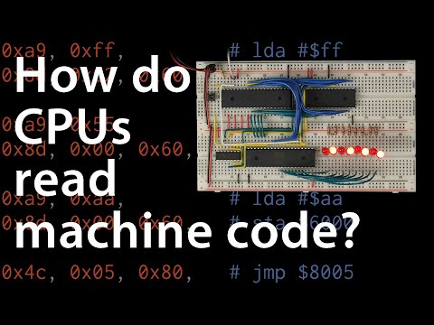
Building on the bare 6502 from part 1, this lecture replaces hard-wired no-op instructions with a programmable EEPROM, so the processor can finally fetch real, changeable instructions. It walks through address decoding, why only half of the address space is used for ROM, and how the 6502's reset vector tells the processor where a program starts.
The second half introduces the 65C22 Versatile Interface Adapter (VIA), a companion chip that lets the processor talk to the outside world through latched output ports. By the end, the circuit runs a small hand-written machine code program that writes alternating bit patterns to eight LEDs in a loop, the first genuinely interactive output from the build.
Key ideas
- EEPROM address decoding: because the 28C256 EEPROM has 15 address lines but the 6502 has 16, the top address line (
A15) is used to enable the chip only for the upper half of the address space, so the reset vector at$FFFC/$FFFDlands inside the ROM. - Chip enable via NAND-as-inverter: a NAND gate with its inputs tied together acts as an inverter, turning
A15into an active-low chip-select signal for the EEPROM. - Little-endian addresses: the 6502 stores 16-bit addresses low byte first, so a jump target of
$8000is written in the program as bytes00, 80. - Writing vs. reading on the bus: the processor uses the same address and data lines for both instruction fetches and data output, so writing to an address is only meaningful if some hardware is listening at that address.
- Address decode + latch: any output device needs decode logic to recognize its address and a latch to hold the data after the processor moves on, which is exactly what the 65C22 VIA provides.
- Data direction registers: each pin of the VIA's port A and port B can be individually configured as input or output by writing a bitmask to a data direction register before using the port.
- Register select lines: four register-select pins on the VIA, driven from the low address bits, choose which of its 16 internal registers (such as port B or its data direction register) the processor is addressing.
- Address space trade-offs: the decode logic deliberately ignores several address bits, wasting address range but saving logic gates, a cost/complexity trade-off the lecture treats as a real engineering decision.
Walkthrough
Wiring the EEPROM into the address and data bus (1:00)
The 28C256 EEPROM's 15 address lines are connected to the processor's A0-A14, and its 8 data lines to the processor's data bus. Because the EEPROM only covers half the 6502's address range, its chip-enable pin is wired through an inverted A15 so that it only responds to addresses $8000 and above, keeping the reset vector inside programmable memory.
Programming the EEPROM with Python and testing no-ops (8:00)
A short Python script builds a 32,768-byte ROM image filled with the no-op opcode $EA and writes it with an EEPROM programmer. Single-stepping the clock (monitored again through the Arduino from part 1) confirms the processor reads the reset vector from the EEPROM and starts fetching no-ops from $8000 onward, reproducing part 1's behavior but from real memory instead of hard-wired resistors.
Writing a first real program: load and store (15:09)
Using the 6502's opcode table, the lecture builds a tiny program: LDA #$42 (opcode A9) loads a value into the accumulator, then STA $6000 (opcode 8D) writes it to an address. Single-stepping shows the processor set the address bus to $6000 and drive the value $42 onto the data bus itself, rather than reading it, which raises the question of what, if anything, is listening at that address.
Introducing the 65C22 VIA for output (22:10)
The lecture explains that any output device needs address-decode logic plus a latch, and introduces the 65C22 VIA as a chip that provides both, alongside ports A and B, register-select lines, and a data-direction register per port. Wiring covers chip-select logic built from NAND gates (reusing one already used for the EEPROM), the clock, read/write, reset, data bus, and register-select lines tied to the low address bits.
Configuring port B and driving LEDs (37:25)
Eight LEDs are wired to VIA port B. The program is rewritten to first write $FF to the data direction register (address $6002) to set all of port B's pins as outputs, then alternately store $55 and $AA to port B (address $6000) with a jump instruction looping back, producing an alternating LED pattern.
Assembling, reprogramming, and verifying step by step (43:28)
After fixing a Python syntax error, the final ROM image is inspected as a hex dump, reprogrammed onto the EEPROM, and run. The LEDs immediately flip between the two bit patterns. The lecture then reconnects the Arduino monitor and single-steps through the whole program once more, confirming each load, store, and jump instruction against what appears on the address, data, and read/write lines.
Before you watch
- Watch part 1 first for the basic 6502 pinout, clock wiring, and reset-vector behavior this video builds on.
- Comfort reading hexadecimal and binary values, and following an opcode table, is assumed.
- Basic familiarity with NAND gates as logic building blocks is useful for the address-decode sections.
Check your understanding
- Why does the EEPROM only respond to the upper half of the 6502's address space, and how does that keep the reset vector inside ROM?
- What two things does any output device connected to the 6502's bus need, and which chip provides both in this build?
- Why must the data direction register be configured before writing meaningful output to VIA port B?
- Explain why the program's jump target and the reset vector bytes appear "backwards" in the ROM image.
- What trade-off does the lecture describe in choosing not to decode every address bit for the VIA's chip select?
Vocabulary
- EEPROM (noun)
- A memory chip that keeps its stored data even without power and can be reprogrammed.
An EEPROM replaces the hard-wired no-op with real instructions. - address decoding (noun)
- The circuit logic that figures out which chip should respond to a given address.
Address decoding ensures only the EEPROM answers for its address range. - chip enable (noun)
- A signal that turns a chip on so it can be read from or written to.
The chip enable pin is driven by the inverted top address line. - inverter (noun)
- A circuit that flips a signal from high to low or low to high.
A NAND gate is wired as an inverter for the enable signal. - little-endian (adjective)
- Describing a way of storing numbers with the smallest byte first.
The 6502 stores addresses in little-endian order. - latch (noun)
- A circuit that holds onto a value even after the input signal changes.
An output device needs a latch to hold the data written to it. - port (noun)
- A group of pins on a chip used together to send or receive signals.
The VIA's port B connects to the LEDs. - data direction register (noun)
- A register that sets whether each pin of a port acts as an input or an output.
The data direction register must be set before using port B. - register select (noun)
- Signal lines that choose which internal register of a chip is being addressed.
Register select lines pick which VIA register the processor talks to. - accumulator (noun)
- The main register in a processor used for holding values during calculations.
LDA loads a value into the accumulator. - bitmask (noun)
- A pattern of bits used to set or check specific bits in a value.
A bitmask configures which pins are outputs. - trade-off (noun)
- A choice where gaining one benefit means giving up another.
Ignoring some address bits is a trade-off between simplicity and wasted space. - hex dump (noun)
- A printed listing of a file's bytes shown in hexadecimal.
The final ROM image is inspected as a hex dump. - loop (noun)
- A section of code that repeats over and over.
A jump instruction creates a loop that alternates the LED pattern. - programmable (adjective)
- Able to be given new instructions or data after manufacturing.
An EEPROM is programmable, unlike a fixed resistor network. - interactive (adjective)
- Able to respond to input or produce a visible reaction.
The LED output is the first interactive result from the build. - companion chip (noun)
- An extra chip added alongside the main processor to add capabilities.
The VIA is a companion chip that handles output. - reprogram (verb)
- To write new instructions into a memory chip, replacing the old ones.
The EEPROM is reprogrammed after fixing the bug. - syntax error (noun)
- A mistake in code that breaks the required grammar of the language.
A Python syntax error is fixed before the final run. - verify (verb)
- To confirm that something works as expected.
Single-stepping helps verify each instruction against the bus.
Chapters
- 0:00 <Untitled Chapter 1>
- 0:06 6502 Microprocessor
- 1:16 Pinout for the Eeprom
- 5:52 Output Enable
- 10:19 The Eeprom Programmer
- 17:43 Run the Python Script To Regenerate the Rom File
- 21:00 Output Hardware
- 25:32 Chip Select
- 30:21 Address Decode
- 33:03 Clock Signal
- 33:22 Reset Pin
- 33:33 Reset Circuit
- 34:38 Register Select Pins
- 39:42 Data Direction Registers
- 41:50 Create a Loop
- 42:05 Op Code for the Jump Instruction
- 43:28 Syntax Error
- 43:38 Hex Dump
From the YouTube description
Schematics, datasheets, kits, and more at https://eater.net/6502
Part 1: https://www.youtube.com/watch?v=LnzuMJLZRdU
Part 2: This video!
Part 3: https://www.youtube.com/watch?v=oO8_2JJV0B4
Part 4: https://www.youtube.com/watch?v=FY3zTUaykVo
Part 5: https://www.youtube.com/watch?v=xBjQVxVxOxc
Part 6: https://www.youtube.com/watch?v=i_wrxBdXTgM
Part 7: https://www.youtube.com/watch?v=omI0MrTWiMU
Support these videos on Patreon: https://www.patreon.com/beneater or https://eater.net/support for other ways to support.
------------------
Social media:
Website: https://www.eater.net
Twitter: https://x.com/beneater
Patreon: https://patreon.com/beneater
Reddit: https://www.reddit.com/r/beneater
Special thanks to these supporters for making this video possible:
Adam Lininger
Alex Catchpole
Andrew R. Whalley
Anthony Cuccia
Armin Brauns
BakerStaunch
Beau-James Erion
Ben Dyson
Ben Kamens
Ben Williams
Bradley Pirtle
Brian Wanda
Carlos Ambrozak
Christopher Blackmon
Clayton Parker Coleman
Daniel Tang
Dave Walter
David H. Friedman
David Turner
Dean Winger
Debilu Krastas
Dušan Dželebdžić
Dzevad Trumic
Eric Brummer
Eric Dynowski
Eric Twilegar
Erik Broeders
Eugene Bulkin
Foaly
fxshlein
Gabriel Lafond-Thenaille
HaykH
hunter wright
Ian Tait
Ivan Sorokin
Jackson Warren
JavaXP
Jay Binks
Jayne Gabriele
Jeremy A.
Jeremy Wise
Jimmy Campbell
Joel Messerli
Joel Miller
Joern Heidenreich
Jordan Scales
Joshua King
Justin Dubs
Justin Duch
Kent Collins
Manne Moquist
Marcus Classon
Mats Fredriksson
Michael
Michael Burke
Michael Garland
Michael Tedder
Miguel Ríos
Nathan Wachholz
Nicholas Moresco
Nick Sutton
Nick Wrightsman
Onion Sniffer
Paul Pluzhnikov
Paul Randal
Peter Simard
Randy True
Rob Bruno
Robert Blackshaw
Robert Butler
Sachin Chitale
Scott
Sergey Ten
SonOfSofaman
Stefan Nesinger
Stefanus Du Toit
Stephen Smithstone
Steve Jones
Steve Gorman
Steven Pequeno
Thomas Ballinger
Tom Burns
Vladimir Kanazir
Warren Miller
xisente
Örn Arnarson
← Part 1: 'Hello, world' from scratch on a 6502 · Part 3: Assembly language vs. machine code →